USER PORT
User Port Extension Header
Pin |
Name |
Description |
Special Purpose |
|---|---|---|---|
1 |
GND |
Ground |
|
2 |
+5V |
+5 VDC (200 mA max) |
|
3 |
/RESET |
Reset, will force a Cold Start. Also a reset output for devices. |
|
4 |
CNT1 |
Counter 1, from CIA #1 |
|
5 |
SP1 |
Serial Port 1, from CIA #1 |
|
6 |
CNT2 |
Counter 2, from CIA #2 |
|
7 |
SP2 |
Serial Port 2, from CIA #2 |
|
8 |
/PC2 |
Handshaking line, from CIA #2 |
|
9 |
ATN |
Serial Attention |
|
10 |
12VDC |
12VDC (Max 500mA) |
|
11 |
12VDC |
12VDC (Max 500mA) |
|
12 |
GND |
Ground |
|
13 |
USRCTL0 |
FPGA Pin, NOT 5V tolerant! |
LED Clock |
A |
GND |
Ground (RS232: GND) |
|
B |
/FLAG2 |
Flag 2 (RS232: RxD=Both B+C) |
|
C |
PB0 |
Data 0 (RS232: RxD=Both B+C) |
|
D |
PB1 |
Data 1 (RS232: RTS) |
|
E |
PB2 |
Data 2 (RS232: DTR) |
|
F |
PB3 |
Data 3 (RS232: RI) |
|
H |
PB4 |
Data 4 (RS232: DCD) |
|
J |
PB5 |
Data 5 |
|
K |
PB6 |
Data 6 (RS232: CTS) |
|
L |
PB7 |
Data 7 (RS232: DSR) |
|
M |
PA2 |
PA2 (RS232: TxD) |
|
N |
GND |
Ground (RS232: GND) |
|
P |
USRCTL1 |
FPGA Pin, NOT 5V tolerant! |
LED Data |
Applies to: Ultimate 64
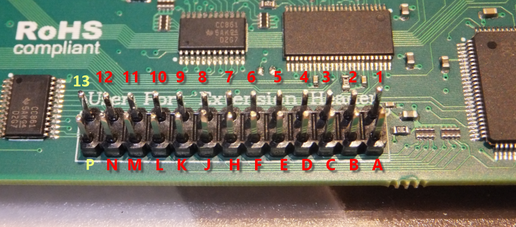
Note that the row 1-12 corresponds to the upper row of the User Port card edge fingers on a C64, and that the row A-N corresponds to the bottom row of the User Port card edge fingers.
Pin 13 and P, the two left most pins on the header, are added for add features to the user port. One of the intended usages of these two pins is the generation of the “9 V~” on the user port extension board.
There is one other use of pin 13 and P, which is the control of a LED Strip. In this case, pin 13 the LED Clock and pin P is the LED Data, assuming a LED strip that is based on APA102C.
In the LED Strip configuration menu, the use of pind 13 and P can be chosen. When the LED Strip is set to ‘off’, the 9 V~ generation is enabled.
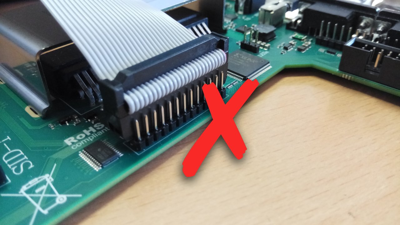
Attaching the User Port Adapter
The user port adapter accessory should be connected using a 26-pin ribbon cable. Note that there is only ONE correct way to connect it, and other ways may result in damage of the U64 itself or to the accessory.
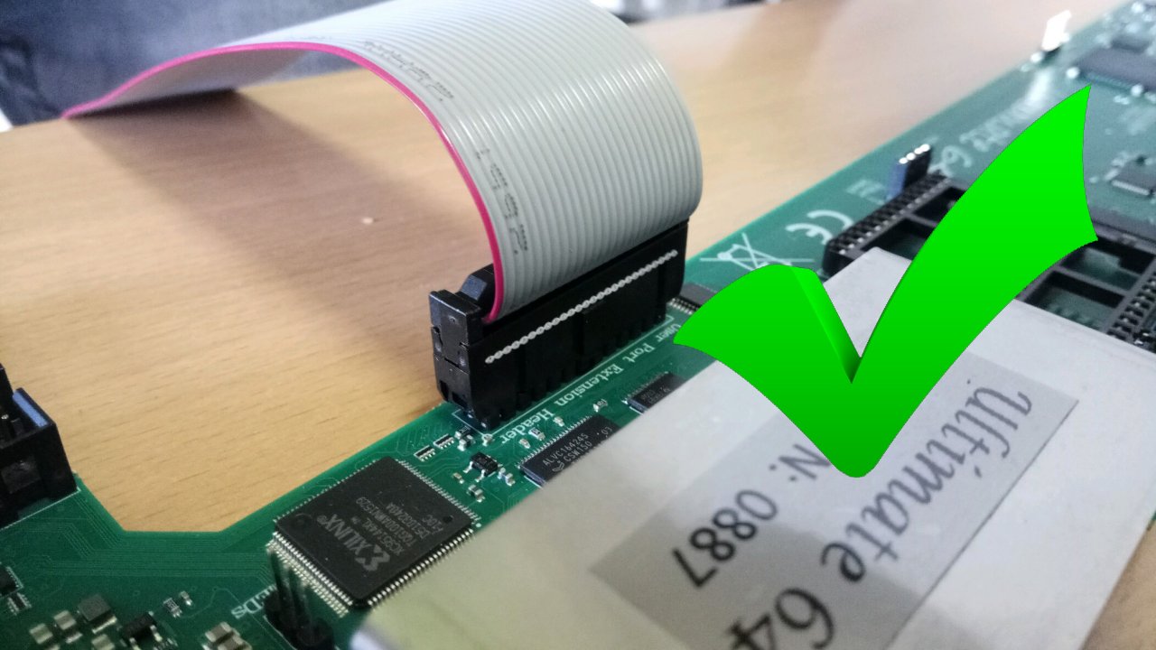
Pay attention to the orientation!! The red wire should line up with pin 1!!!
Please make sure the connector is not shifted a whole row, or to the left or to the right: