Core UCI Architecture
Source basis: Ultimate Command Interface – Register API
Introduction
The ‘Ultimate command interface’ is a feature for the Ultimate based products, ranging from 1541 Ultimate-II all the way to the Commodore 64 Ultimate. It implements a way to communicate to the Ultimate management application programmatically from the Commodore 64, through the cartridge port I/O registers.
The ‘Ultimate command interface’ is the communication layer between the C64 on one side and functional modules of the Ultimate management application on the other side. Such a functional module takes a command, and returns data and status back to the user program on the C64.
There are various ‘command targets’, such as Ultimate DOS, Network, Module Control, SoftIEC Bypass and the new HTTP client, as per firmware version 3.15.
The ‘Ultimate command interface’ feature is accessible from the cartridge I/O range. In this manual, the programming API is described.
Overview
The transport layer of the Ultimate Command Interface makes use of a register interface which is accessible through the cartridge port of the C64. The registers are mapped into I/O space, at the address $DF1B up to $DF1F, masking the last five registers of the RAM Expansion Unit (REU). Mapping this small 5-byte block into the I/O space is optional, and needs to be turned on in the ‘Command Interface’ configuration menu.
Register Overview
The following table shows the four registers and their meaning.
Address |
Description |
Default |
|---|---|---|
$DF1B |
SoftwareIEC Bus ID (Read) |
|
$DF1C |
Control register (Write) |
|
$DF1C |
Status register (Read) |
$00 |
$DF1D |
Command data register (Write) |
|
$DF1D |
Identification register (Read) |
$C9 |
$DF1E |
Response Data register (Read only) |
|
$DF1F |
Status Data register (Read only) |
Communication Protocol Basics
The communication protocol is based on a state machine with four states:
Idle
Command Busy
Data Last (last block)
Data More (more data pending)
The transition through these states takes place in an interaction between the C64 user software and the software running on the Ultimate. The state that the communication protocol is in can be read from the Status register at $DF1C.
Transfer command
When the protocol is in idle state (see paragraph 2.4.2 for the state encoding), the Ultimate is ready to receive a new command. This is done by writing the command byte by byte into the command data register at $DF1D. Then, the command is pushed into the Ultimate by writing a ‘1’ to the control bit ‘PUSH_CMD’, in the control register. This will cause a state transition to “Command Busy”.
Ultimate processes command
As soon as the Ultimate has decided how to respond to this command, it will prepare the data and status reply, and cause the state machine to move to one of the two data states: ‘Data Last’, or ‘Data More’.
Reading the reply
The user software can now read both data and status from the respective registers $DF1E and $DF1F. Whether there is data or status available can be seen from the upper two bits of the status register. These bits will be ‘1’ when there is still more data to be read, and ‘0’ otherwise.
Release: Accept data
As soon as the software has read all the data (or decides not to do so), the C64 should write a ‘1’ to the register bit ‘DATA_ACC’, to indicate that all data was accepted. If this was the last data block, this causes the state machine to go back to the idle state, or else, the state returns to “Command Busy”.
State machine
The following diagram shows the state machine:
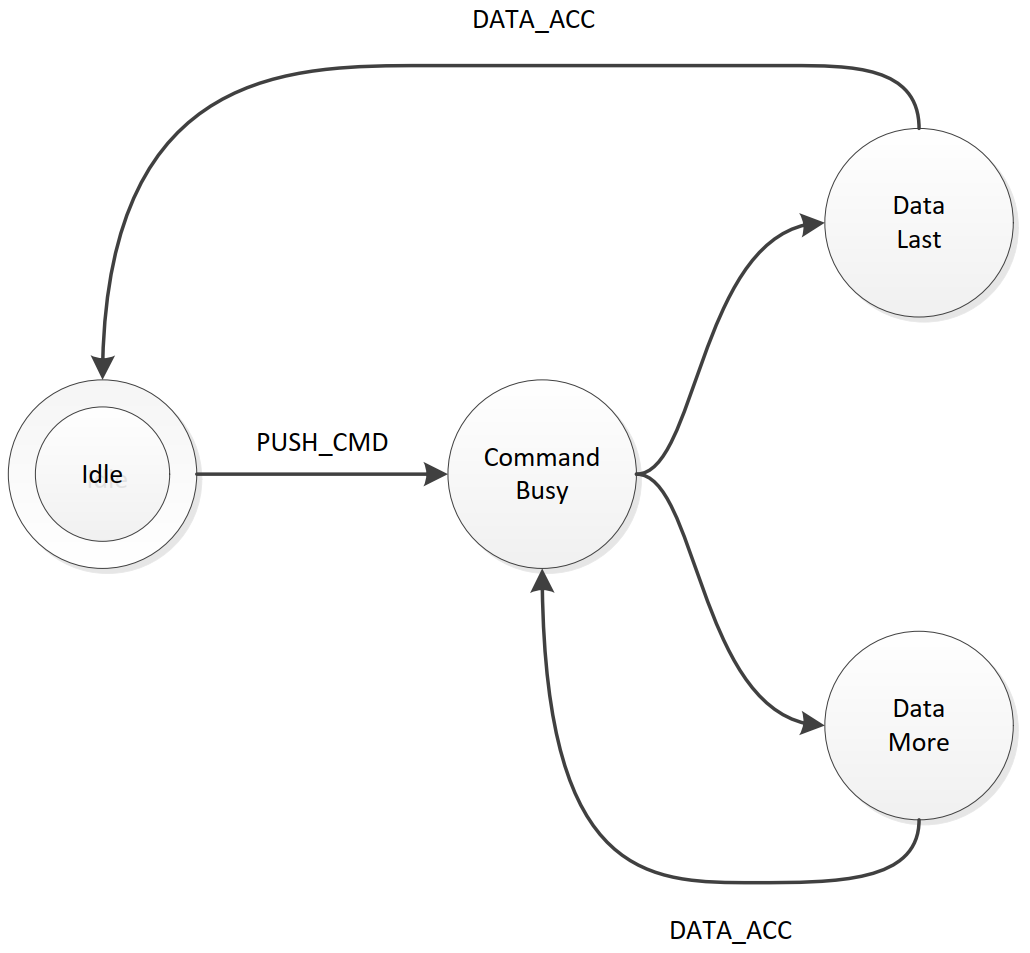
Basic Protocol State Machine
Note: Setting the ‘ABORT’ bit, does not directly influence the state machine. It is handled by the Ultimate software, which will in turn reset the state machine to idle eventually.
Register details
Control register
The control register contains the following bits:
Bit 7 |
Bit 6 |
Bit 5 |
Bit 4 |
Bit 3 |
Bit 2 |
Bit 1 |
Bit 0 |
|---|---|---|---|---|---|---|---|
DMA |
TRIGGER |
IRQ |
reserved |
CLR_ERR |
ABORT |
DATA_ACC |
PUSH_CMD |
PUSH_CMD: Writing a ‘1’ to this register bit causes the command that was written to the command data register to be pushed into the software of the Ultimate.
DATA_ACC: Writing a ‘1’ to this register bit tells the communication layer that all data from the Ultimate was accepted. This is automatically ignored when the communication controller is not in one of the two data states. Writing to this bit also causes the transfer of the data/status queues to be aborted and reset. Thus, the data response and status response queues will be empty after writing this bit.
ABORT: Writing a ‘1’ to this register sets the ‘abort’ flag in the communication controller. This bit is polled by the Ultimate software. When it finds this bit set, the current communication is aborted, and the state machine is forced back to the idle state.
CLR_ERR: Pushing a command to the Ultimate when the communication layer is not in idle mode, causes a state error flag to be set. See status register. Write a ‘1’ to CLR_ERR to clear this error condition.
IRQ: (Starting from firmware V3.15): Setting this bit to ‘1’ enables the interrupt generation for the completion of the command. This allows the software to do other things than to wait for the state bits to transition to the data state. This bit is automatically cleared when the response queues are read or when the DATA_ACC bit is set. Whether the Command Interface is generating an interrupt or not is reflected by bit 7 of the identification byte. Normally this reads $C9; when an IRQ is active it reads $49, with bit 7 cleared.
TRIGGER: When this bit is set to ‘1’ when the command is pushed, the Ultimate will enter DMA mode as soon as $FF00 is written. DMA mode is released when the command is done.
DMA: When this bit is set to ‘1’ when the command is pushed, the Ultimate will enter DMA mode immediately. DMA mode is released when the command is done.
Status register
The status register contains the following bits:
Bit 7 |
Bit 6 |
Bit 5 |
Bit 4 |
Bit 3 |
Bit 2 |
Bit 1 |
Bit 0 |
|---|---|---|---|---|---|---|---|
DATA_AV |
STAT_AV |
STATE |
STATE |
ERROR |
ABORT_P |
DATA_ACC |
CMD_BUSY |
CMD_BUSY: This bit indicates that there is a pending command in the command memory.
DATA_ACC: This bit reflects the condition that the user has told the Ultimate that it accepted the data.
ABORT_P: This bit reflects the state of the internal abort flag. When this bit is ‘1’, the Ultimate still has to handle the abort request.
ERROR: When this bit is ‘1’, the user tried to send a command to the Ultimate while it was not in idle state.
STATE: These two bits encode the protocol state:
00: Idle
01: Command Busy
10: Data Last
11: Data More
STAT_AV: When this bit is ‘1’, there is status data available from the status queue, accessible through the status data register ($DF1F).
DATA_AV: When this bit is ‘1’, there is response data available from the data queue, accessible through the response data register ($DF1E).
Queues
As previously described, there are three byte-queues that the Ultimate Command Interface uses:
Command queue
Response Data queue
Status queue
The sizes of these queues are important to note, since they define the maximum transfer size per command. The command queue size is 896 bytes ($380), the response data queue is also 896 bytes ($380), and the status queue is 256 bytes ($100).
On top of the transport layer, there is light weight dispatcher. This dispatcher sends the command from the user software to a functional module in the Ultimate management application. The first byte of the command is determines the destination. Such a destination is called a ‘target’.
Initially, in version 2.6 of the Ultimate firmware, there is only one functional target: “Ultimate-DOS”. Two instances of this DOS are located at targets 1 and 2. See the documentation of this target to obtain more information on the commands this target implements. Later versions add more targets to enrich the functionality with network access, and much more.