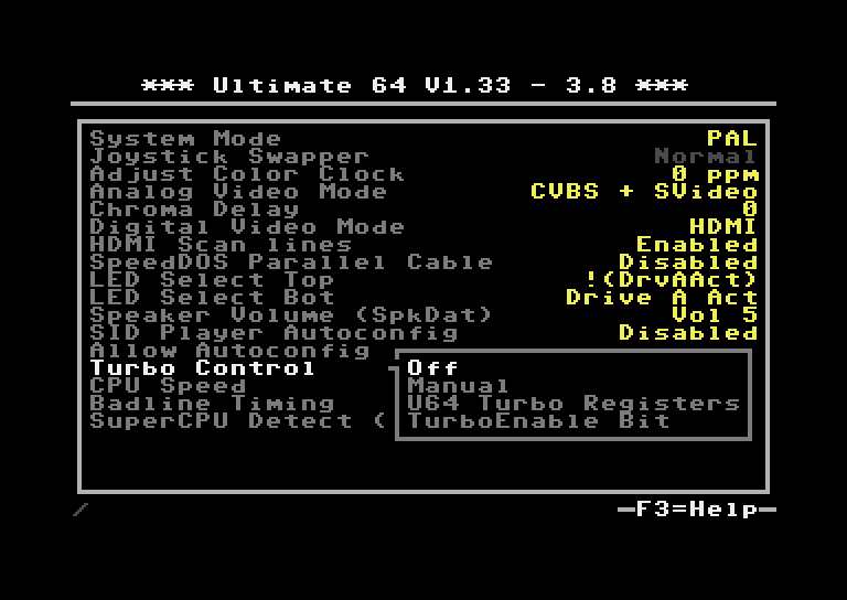
Turbo mode settings
Turbo control
Option |
Description |
|---|---|
Off |
Turbo control is off |
Manual |
Turbo control uses settings from U64. Settings CANNOT be altered with registers. |
U64 Turbo Registers |
Turbo control uses settings from U64. Settings CAN be altered with registers. See Turbo Control registers. |
TurboEnable Bit |
Turbo control uses settings from U64. Settings CAN be altered with registers. See Turbo Control registers. |
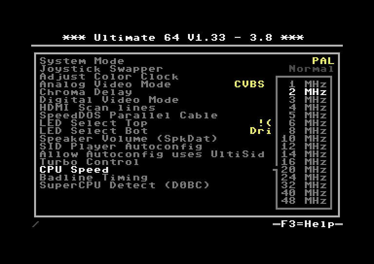
CPU Speed
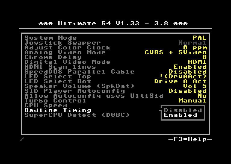
Badline Timing
SuperCPU Detect ($D0BC)
Turbo Control registers
Address |
Description |
|
|---|---|---|
53297/$D031 |
U64 Turbo Control This register is only available when the Turbo Mode selector is set to ‘U64 Turbo Registers’ or ‘Turbo Enable Bit’. Otherwise it simply reads $FF.
Note that the CPU and memory subsystem run at 48 MHz (U64) or 64 MHz (U64E2), and that this turbo setting determines how many of the available time slots are assigned to the CPU. When the VIC is enabled, it will still steal cycles from these available time slots. Note that the badline timing setting does not have influence on the BA signal on the cartridge port. This means that when accesses to external devices are made, you will still run into the badline limitations. This also applies to having the SID sockets enabled and doing accesses to the SID registers. |
|
CPU Speed (index) - U64
|
CPU Speed (index) - U64E2
|
|
53296/$D030 |
Turbo Enable Bit This register is only available when the Turbo Mode selector is set to ‘Turbo Enable Bit’. Otherwise it simply reads $FF.
|
|
53370/$D07A |
SuperCPU compatible enable/disable registers This register is only available when the Turbo Mode selector is set to ‘U64 Turbo Registers’ or ‘Turbo Enable Bit’. This register is write only
More information: https://www.c64-wiki.com/wiki/SuperCPU |
|
53371/$D07B |
SuperCPU compatible enable/disable registers This register is only available when the Turbo Mode selector is set to ‘U64 Turbo Registers’ or ‘Turbo Enable Bit’. This register is write only
More information: https://www.c64-wiki.com/wiki/SuperCPU |
|
53436/$D0BC |
SuperCPU Detect ($D0BC)
This register is only available when it is separately enabled. This register is read only More information: https://www.c64-wiki.com/wiki/SuperCPU |
|
Notes on Bad Lines in Turbo Mode
In the U64 design, the VIC will always get priority, regardless of the badline setting. This allows the VIC to produce correct graphics while turbo is on, unlike the C128 which cannot display VIC graphics in 2 MHz mode.
On a regular C64, there are two time slots per MHz; PHI2=0 and PHI2=1. Normally, the VIC accesses the RAM during PHI2=0, and lets the CPU do the access while PHI2=1; with the exception of VIC DMA. On every line VIC DMA happens for a few cycles when sprites are enabled and every 8 lines during a raster scan to load 40 bytes of character data => that’s why they are called “bad” lines, since the CPU is blocked for 43 µs.
Whenever the VIC requires a cycle from the CPU (PHI2=1), the BA (bus available) signal becomes low. This tells the cartridge that no DMA cycle can take place during that time, and internally the 6510 is also halted. The badline setting in the U64 doesn’t change the behavior of the BA signal at all, and the reason for this is that when the VIC does a memory access, it may access an external device on the cartridge port, for instance when playing a cartridge game with graphics stored in EPROM, so it needs to reserve the cycles on the external bus for this purpose.
On the U64, there are 48 time slots per MHz, and on the C64U even 64. In all of these time slots a memory byte can be read, as long as the memory is internal. As soon as an access needs to be done to the external bus, it will request the cartridge bus bridge to access the external resource. This always works at 1 MHz. Plus, as previously discussed, such an access can only take place when ‘bus available’ is ‘1’, thus for all cycles in which it is certain that the VIC will not access the memory.
What does the badline setting do? Well, the only thing it does is that it allows the CPU to finish its cycle, if it turns out that it had access to the memory, regardless of the BA signal. When badlines are enabled, the CPU is halted during BA=0, which makes the timing compatible with a regular C64. When badlines are disabled, the CPU can continue even when BA=0, given that the access is to an internal address.
(Applies to: Ultimate 64 and Ultimate 64 Elite-II)
*) Setting are only available on the Ultimate 64, firmware >= 1.33*